


SLED 3.6
SLED improves the user experience by allowing to:
- show/hide instance pin of instance elements in a schematic to simplify the schematic and improve its readability when a pin is optional
- set the color of instance elements in a schematic by TCL script to change the graphical representation of an instance depending on its parameter values
- define tags in parameter definition to bring order when a cell contains tens of parameter
- filter the parameter by tag in the property editor to highlight certain parameters according to their meaning/usage
SLED 3.5
SLED 3.5.0 enables greater configurability thanks to the new possibility for the users of being able to define TCL functions related to a cell called on hooks.
SLED 3.4
- SLED 3.4 provides the new feature of lock/unlock a library.
- SLED 3.4 enhances the cell display organization in libraries by providing the availability to use hierarchical tags.
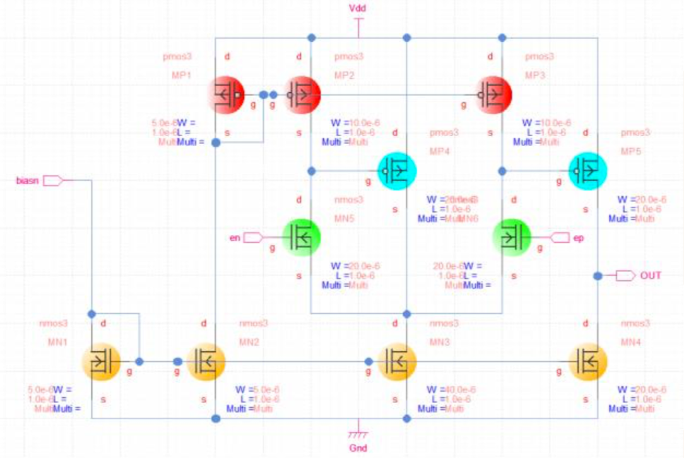
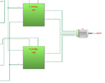
SLED 3.3 - Make schematics meaningful with colors
SLED 3.3 enables background coloring and patterning of each individual symbol instance. This feature aims to make schematic more meaningful by enabling easy customization of symbol instances of a same cell.
SLED 3.2 - Engage migration of sled parameters
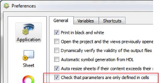
For preparing the migration towards a future release of SLED which will allow multi-level schematics, SLED 3.2 will detect the incoming incompatibilities like parameter definitions inside a project, a library, a symbol or a schematic.
In future releases of SLED, parameter definitions will only be allowed in the cells. Parameter definitions detected in projects, libraries, schematics or symbols will then be automatically migrated into cells.
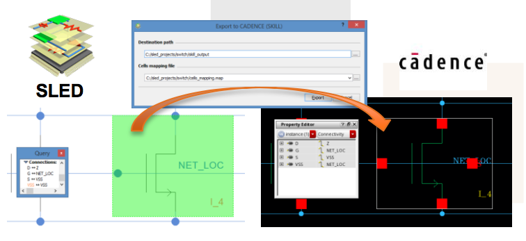
SLED 3.1 - Export schematics to cadence
To improve the interoperability of the Dolphin Solutions, SLED 3.1 provides a command to convert a SLED design (Libraries, Cells, Schematics, Symbols) into a CADENCE Virtuoso design.
SLED 3.0 - 64-bit native application
Starting from now, all our EDA solutions will only be available in 64-bit versions for x86_64 platforms with Microsoft Windows Vista/7/8/10 or with RedHat Enterprise Linux 6 (RHEL6) and compatible Linux distributions.
Native 64-bit applications allow to overcome the limitations of 32-bit versions, such as loading large designs and simplifying installations on a 64-bit Linux OS.
SLED 2.7 - On the road towards slash
SLED 2.7 significantly improves its ergonomics with new graphic net attributes, with an easier access to tutorials and with a new installer.
SLASH, merging SLED with SMASH, will provide an integrated user experience with a unified user interface for schematic driven simulation.
SLED 2.6 - On the road towards slash
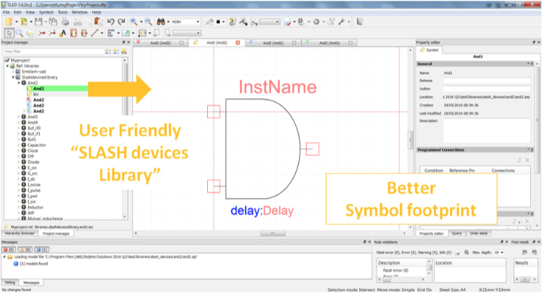
SLED 2.6 notably delivers an enhanced and user friendly device library for fast edition of mixed-signal and multi-language designs as well as improved EDIF interoperability.
SLASH, merging SLED with SMASH, will provide an integrated user experience with a uni ed SLASH user interface for schematic driven simulation.
SLED 2.5 - For better interoperability
Continuing the improvements for interoperability and schematic editing efficiency, SLED 2.5 provides two main features:
- EDIF export of schematics to Cadence Virtuoso, complementing already available EDIF import
- Reduced internal changes in SLED project files when performing multiple saves for better cohabitation with versionning tools
These features improve the interoperability of SLED with standard practices and tools. SLED 2.5 also delivers ergonomics and ease of use enhancements to constantly improve the overall user experience and productivity.
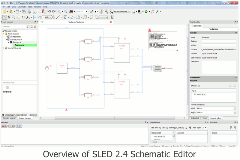
SLED 2.4 - For better interoperability
To enable electronic design for a given process, foundries provide a Process Design Kit (PDK) containing all the files needed to design. For helping PDK integration, SLED 2.4 provides a PDK import feature which enables fast and easy building of a SLED PDK.
This feature paves the way for better interoperability of SLED with standard practices and tools. SLED 2.4 also delivers ergonomics and ease of use enhancements to constantly improve the overall user experience and productivity.
SLED 2.3 - SLASH in the lens
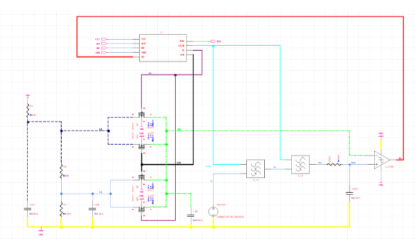
In the continuity of the reinforcement of the link between SLED and SMASH, SLED 2.3 notably improves the capability to add simulation directives directly in the schematic. Designers can integrate simulator control directives into top-level schematics, paving the way to the setup of the testbench and the configuration of all simulations directly from the schematic editor SLED.
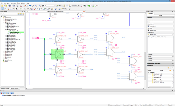
SLED 2.2 - On the road towards SLASH
The link between SLED and SMASH is continually enhanced to deliver an integrated user experience with a unified SLASH interface providing simulation configuration and waveform viewing.
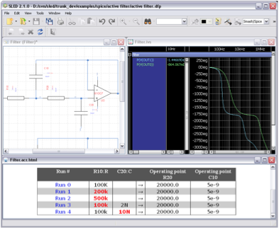
SLED 2.2 notably enables displaying, with a graphic overlay in the schematic, data back-annotated from SMASH operating-point results.
SLED 2.2 also improves the integration of the waveform viewer.
SLED 2.1: Verilog Import - Smart Wiring
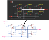
SLED 2.1 provides a new hierarchy browser to quickly and easily display and navigate the design hierarchy depending on the active design context configuration, along
with the capability to import structural Verilog modules as schematics in order to simplify reuse of existing HDL structural assemblies.
SLED 2.1 also delivers ease of use enhancements, such as smart wiring and pasting as matrices, to constantly improve the overall user experience and productivity of
designers.
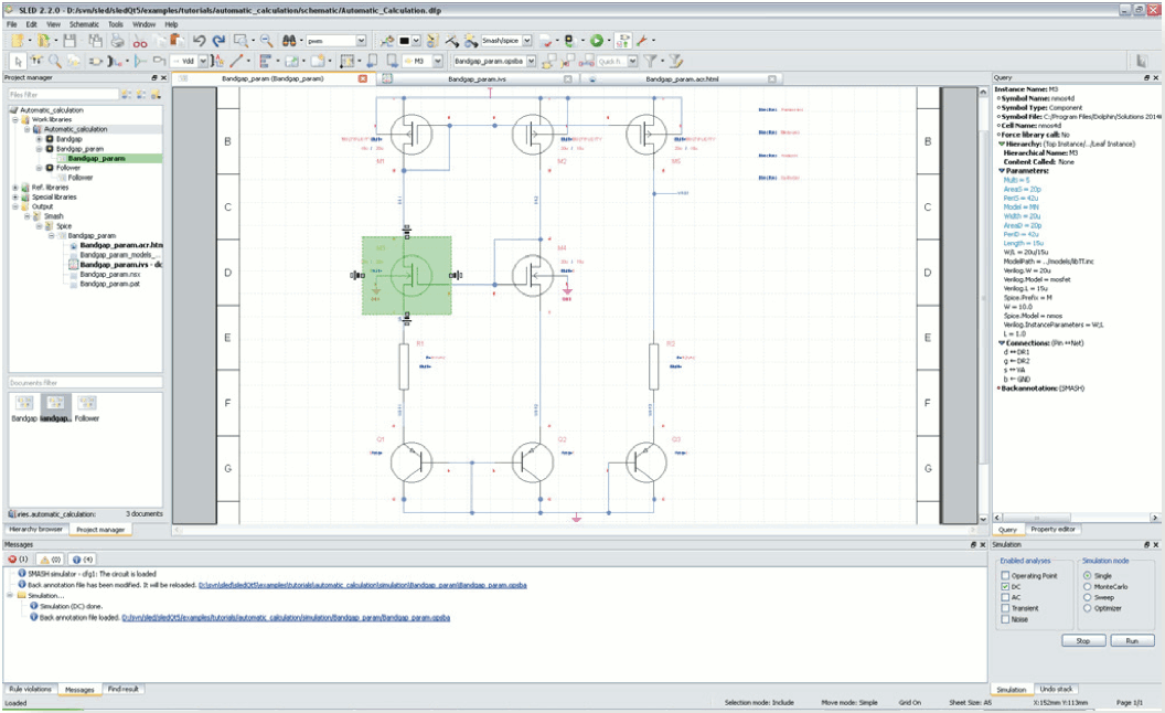
SLED 2.0: Increased Link with SMASH Simulator - Efficient Schematic Edition
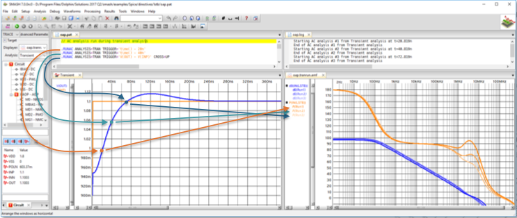
SLED 2.0 extends the link between the schematic editor and the mixed-signal simulator SMASH by providing the means to automatically re-run simulations following
parameter updates in the schematic to achieve the optimized design goals.
SLED 2.0 also delivers ergonomics and ease of use enhancements to constantly improve the overall user experience and productivity.
SLED 1.11: Improved Ergonomics for Schematic Design
SLED 1.11 provides ergonomics and ease of use enhancements to constantly improve the overall user experience. Additionally, important progress has been made on the robustness of SLED with advanced techniques to automatically validate the user interface.
SLED 1.10: Improved ergonomics for schematic design
SLED 1.10 provides many ease of use enhancements to simplify the creation and modification of schematics such as resizing, mirroring, rotating, text editing...
SLED 1.10 also provides a completely new drag feature allowing to efficiently rearrange schematic elements while maintaining connectivity to create great
schematics. User feedback and suggestions on this new drag will enable fine tuning the behavior for best results.
SLED 1.9: Improved Model Management
Each new release of the schematic editor SLED focuses on improving the user experience for efficiently creating mixed-signal, multi-level and multi-language hierarchical schematics which can also be used in project reports or for communication purposes with customers.
SLED 1.8: Multi-level and multi-domain modeling
Multi-level modeling is essential to be able to simulate complex subsystems in a reasonable amount of time and even to make simulations feasible. SLED 1.8 focuses on delivering relevant features for smoother model management and browsing as well as for flexible mixed-signal and multi-domain netlisting.
On top of that, this release of SLED also provides the means to set directives directly in the schematic in order to create more complete testbenches. The directives can be parameterized from the property editor and selectively enabled or ignored during netlisting depending on the design context.
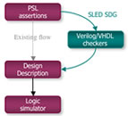
SLED SDG: The solution for bug trappers
SLED SDG (Synthesizable Detector Generator) is dedicated to improving productivity when using assertions by providing automatic generation of RTL checkers (Verilog or VHDL) from PSL (Property Specification Language) assertions. Such checkers can be used both for virtual test and in-circuit embedded test!
SLED 1.7: Productivity, Ergonomics, Design Checking
SLED 1.7 will satisfy the expectations of many designers as it includes significant user interface enhancements, as well as new features allowing to simplify the
creation of advanced schematics with bus expressions, programmable pass-thru net connections... The verification of designs is significantly extended with custom
design rules using the integrated Design Rule Checker.
SLED 1.7 increases designer productivity and enables automating design verification!
SLED SDG: Assertion-based Verification with PSL
As design verification takes so much of designers' time at the various stages of new product development, the top productivity enhancement solution is that which best helps improve the RoI for quality checks.
SLED 1.6: Ease of Use, User Interface, Netlisting
Release 1.6 of the Schematic Link Editor SLED emphasizes on ease of use and on the graphic user interface. It delivers solutions facilitating the creation and
verification of designs thanks to libraries, an extended Design Rule Checker, a search facility... while enhancing team work awareness.
SLED 1.6 paves the way for efficient graphic assembly of multi-level and multi-domain designs!
SLED 1.5: Hierarchical, Design Rule Checker and PSL Assertions
Third generation Schematic Link Editor, SLED, helps increase designers' productivity with graphic link and configuration entry for plugging assertion-based checks and
easing hierarchical verification. As verification takes most of designers' time, this release of SLED increases design robustness while decreasing verification time
thanks to assertions in PSL (Property Specification Language) and efficient Design Rule Checks.
SLED 1.5 improves design robustness and enhances the design verification process!
SLED 1.2: Schematic Link EDitor
Schematics Edition had lost its luster for lack of innovation which resulted in the perception that Hardware Description Languages had made it obsolete. But the essence
of any conceptualization can only be graphical: any designer thinks in images, not in words.
Beyond the traditional bottom-up practice of interconnecting analog or logic primitives, in view of the top-down techniques needed for mixed signal and multi-domain
designs, SLED 1.2 paves the road to the Schematics Editor of the third generation embedding the Link-Edit capability of Hardware Description Languages.
SLED 1.1: Schematic Link EDitor
Schematics Edition had lost its luster for lack of innovation which resulted in the perception that Hardware Description Languages had made it obsolete. But the essence
of any conceptualization can only be graphical: any designer thinks in images, not in words.
Beyond the traditional bottom-up practice of interconnecting analog or logic primitives, in view of the top-down techniques needed for mixed signal and multi-domain
designs, SLED 1.1 performs the transition to the Schematics Editor of the third generation embedding the Link-Edit capability of Hardware Description Languages.
SLED 1.0: Schematic Link EDitor
SLED is a hierarchical schematic entry solution of the third generation which delivers the long awaited dual capability for Graphic Entry and Scriptability at once. It blends efficiently the feasibility of linking components and of writing scripts for configuring a netlist hierarchically. Interoperability with other schematic entry tools is ensured for capitalizing on legacy designs and cooperative work, and interoperability in the Design Chains is ensured through standard design exchange formats and scriptability for customization by CAD managers.
- Highlight